Valve Patent Introduces Optical Eye Tracking with Imaging-Based Angle-Sensitive Detectors
CheckCitation/SourcePlease click:XR Navigation Network
(XR Navigation Network December 20, 2023)eye trackingIt is a process for detecting the position, orientation or movement of the eye. The least invasive method may use one or more optical detectors or sensors to optically track the eye, such as using infrared light to illuminate the entire eye while measuring reflections with at least one optical sensor sensitive to infrared light. Information about how the infrared light is reflected from the eye is analyzed to determine the location, orientation of one or more eye features
In the patent application titled "Optical tracking including imaging-based angle sensitive detectors", V has introduced an optical eye tracking method using imaging-based angle sensitive detectors.
The headset device 405 of FIG. 4 includes hardware sensors for determining the direction in which the user is gazing and additional components, such as one or more eye-tracking components 472 of the eye-tracking subsystem.Said components may be mounted in the vicinity of the display panels 406 and 408 and/or located on the inner surfaces 421 in the vicinity of the optic lens systems 410 and 412, iced for obtaining information about the actual position of the user's pupil 494 .
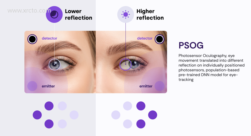
Each eye tracking assembly 472 may include one or more light detectors and optionally one or more light sources, e.g., infrared LEDs.Although four eye tracking assemblies 472 are shown in FIG. 4, a different number of eye tracking assemblies may be provided in practice. Alternatively, each eye tracking assembly 472 includes a light source directed at one of the user's 424 eyes 432 and 434, and a light detector positioned to receive light reflected by the user's respective eye.
FIG. 5 illustrates an example of using multiple eye tracking components. Each eye tracking component includes a light source and light detector and is used to determine the user's gaze position. In the illustrated embodiment, the four eye tracking components 511a-511d of the eye tracking subsystem, collectively referred to as 511, are mounted near the edges of the optical lens 508 and each point toward the pupil 506 of the eye 504 for emitting light toward the eye 504 and capturing light reflected from the iris 502 surrounding the pupil 506.
In this embodiment, the eye tracking component 511 is positioned at the following locations: along the central vertical axis near the top of the optical lens 508, along the central vertical axis near the bottom of the optical lens, along the central horizontal axis near the left side of the optical lens, and along the central horizontal axis near the right side of the display panel. In other embodiments, the eye tracking components 511 may be positioned in other locations and fewer or more eye tracking components may be used.
FIG. 6 depicts a perspective view 600 of an exemplary angle-sensitive optical detector 603. FIG. 7 shows a cross-sectional view 700 of the angle-sensitive optical detector 603 shown in FIG. 6, and FIG. 8 shows a top view 800 of the angle-sensitive optical detector.
In this example, the optical detector 603 includes a quadrant photodetector 604 disposed on a common substrate 602. the quadrant photodetector 604 includes four rimmed regions 604a-604d separated by small gaps. it should be recognized that other types of angle-sensitive detectors may be used.
Angle sensitive detector 603 includes an opaque screen 606 disposed above or in front of photodetector 604. said opaque screen 606 may be coupled to or integrated with said substrate 602. Said opaque screen 606 has an aperture 608 that allows light 616 from the object 614 to pass through. in this embodiment, the object 614 is the user's eye, including a dark pupil 615 of the eye.
The optical detector 603 also includes an imaging lens 610 disposed within an aperture 608 of the opaque screen 606. advantageously, the imaging lens 610 is configured to focus an image 618 of the pupil 615 of the user's eye 614 to the quadrant photodetector.
That is, the imaging lens 610 may be designed to have an object plane that is substantially coplanar with the desired position of the pupil 615 of the user's eye 614 with respect to the imaging lens 610, and an imaging plane that is substantially coplanar with the quadrant photodetector 604.
The active region of each element 604a-604d of the photodetector is available individually, so that light illuminating a single quadrant can be electrically characterized as being within the quadrant only. As light passes through the angle-sensitive detector 603, the energy of the light is distributed between neighboring elements 604a-604d, and the difference in the electrical contribution of each element defines the relative position of the light. A map of the relative intensity distribution of the elements 604a-604d may be used to determine the position of the light illuminating the cell.
As shown, light 616 reflected from the user's eye 614 passes through the lens 610 to form an image 618 of the eye 614.The image 618 contains black spots surrounded by brighter areas due to the darker pupil 615. This is because the darker pupil 615 reflects relatively little light, while portions of the eye 614 and the user's face around the pupil reflect light.
Since the dark pupil 615 will affect the light intensity of the unit, the image 618 formed at the quadrant photodetector 604 may be electrically characterized to determine the position of the pupil 615 relative to the angle sensitive detector 603. The position information may be used for gaze tracking.
FIG. 9 is a simplified view 900 of an imaging lens 610 and an optical detector 603 of an object tracking system. as shown, said imaging lens 610 is configured to focus an image 906 of said object to be tracked 904 onto said quadrant photodetector 604. i.e., the imaging lens 610 may be designed to have a position that is substantially coplanar with the intended position of the object to be tracked 904 with respect to said imaging lens 610 object plane or space, and an imaging plane or space substantially coplanar with the quadrant photodetector 604.
In this way, the units 604a-604d can be used to determine the location of the object 904 in the object space so that said object can be tracked.
FIG. 10A is a perspective view 1000 of an angle-sensitive optical detector 603 and an object 1002 to be detected, wherein said object is located in a first position. Said object 1002 may include a defined pattern 1004 thereon.FIG. 10B is a perspective view of the angle-sensitive optical detector 603 and the object to be detected 1002 of FIG. 10B, wherein said object 1002 is located in a second position.
As shown, the imaging lens 610 receives light 1006 reflected from the object 1002 and produces an image 1008 of the pattern 1004 at the photodetector units 604a-604b. as said object 1004 moves from the first position shown in FIG. 10A to the second position shown in FIG. 10B, the image 1008 of said pattern 1004 moves its position accordingly. The control circuitry may be used to process detector data received from the photodetector units 604a-604b to track the position of the object 1002 in space along one or more dimensions.
In the example shown, the pattern 1004 may be designed to have alternating light and dark portions to help provide more discrete signals at the photodetector units 604a-606b. In at least some embodiments, providing discrete signals may improve the ability of the optical detector 603 to track the object 1002 as the object moves through space along one or more dimensions.
In at least one embodiment, machine learning techniques may be used to support the eye tracking subsystem. For example, a model training portion and an inference portion of the machine learning system may be provided. In the training portion, training data is input to a machine learning algorithm and a trained machine learning model is generated. In the inference portion, runtime data may be provided as input to the trained machine learning model for eye position inference.
The V Society patent titled "Optical tracking including imaging-based angle sensitive detectors" was originally filed in May 2023 and was recently published by the U.S. Patent and Trademark Office.
It should be noted that, in general, after a U.S. patent application is received for examination, it is automatically published 18 months from the filing date or priority date or, at the request of the applicant, within 18 months of the filing date. Note that publication of a patent application does not mean that the patent is granted. After a patent application is filed, the USPTO is required to conduct an actual examination, which can take anywhere from one to three years. Also, a patent application does not necessarily mean that the invention in question will be commercialized.
Related posts


